Making an enclosure [Fabrication]
Saferty Simulator: Authorized Home Security Product
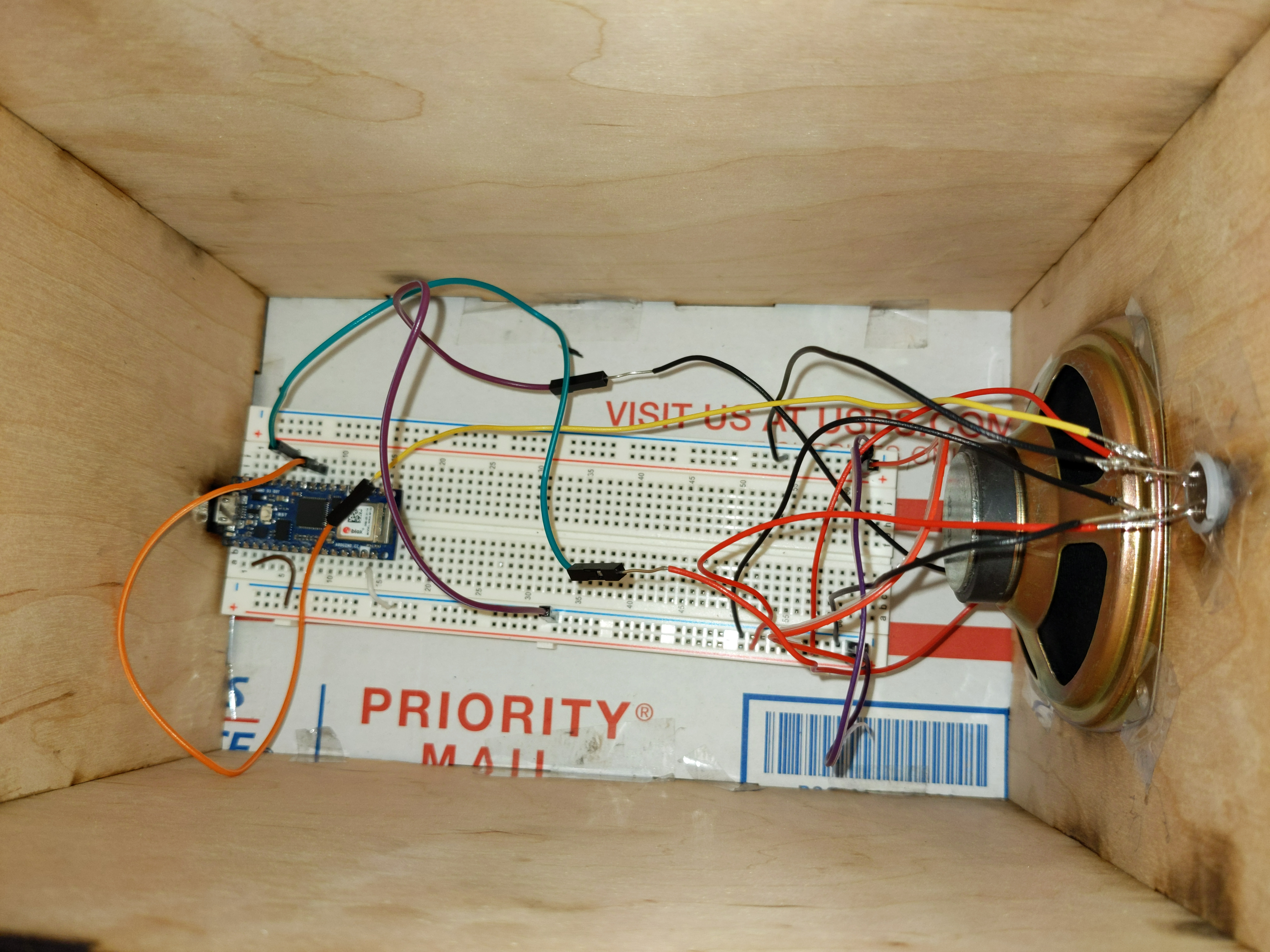
For this week’s assignment to fabricate an enclosure, I worked with a circuit that translate the detection of motion using a PIR sensor to sound with the Arduino tone and pitch functionality.
I started by measuring out my components and designing holes for key elements like the sensor, speaker, and USB input. After constant failure trying to figure out math in general I found an online tool to produce finger joint box vector design called <a href=”https://www.makercase.com/#/>MakerCase</a>. I then cut to cardboard.
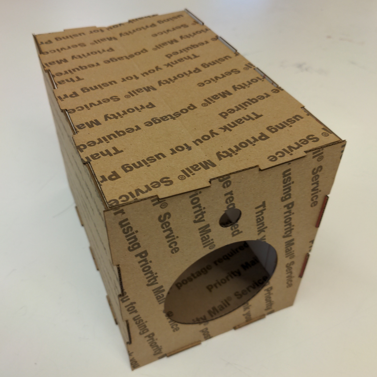
The cardboard cut came out decent but the sensor and USB hole size and placement was a bit off so I took note and made some mild eyeball adjustments. I also notice the finger joints were not level but extended beyong the box’s corner, I figured this was due to how thin the cardboard was (below the 1/8th inch minimum inputted into the box design generating software so I made my small changes and moved on to wood.
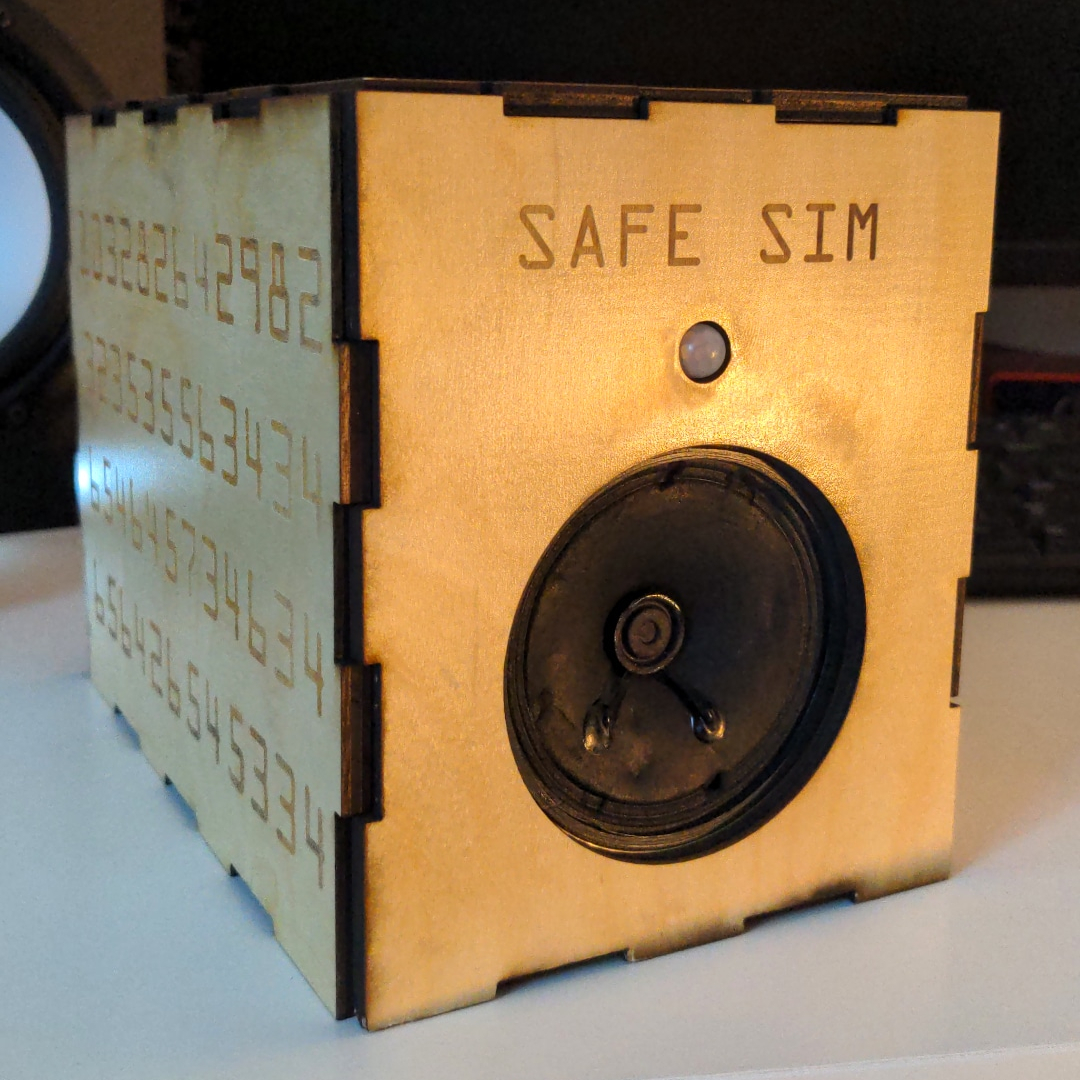
After a tolerance test in which I cut out two 3 inch square and measured the hole and squares, I found the lazer I was using to lose less material than any measurement on my ruler could pick up. I went ahead and cut my adjusted design, finding the slight changes in key holes to be perfect and the joints to be not. I had forgotten to change the material thickness from 1/8th inch to 1/4th inch after prototyping on cardboard so the finger joints don’t quite reach to cover the corners entirely. I was out of wood at this point and tired so I kind of just rolled with it. The laser took quite a few passes to get through my wood so some very dark edges were produced which luckily worked to mask the corner deficiency pretty well.